|
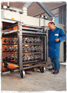 In our vacuum potting machine, inductive components are dried, extracted from gas, moulded in vacuum and hardened with high temperature in a storage oven. The whole process is running fully automatic. In our vacuum potting machine, inductive components are dried, extracted from gas, moulded in vacuum and hardened with high temperature in a storage oven. The whole process is running fully automatic.
Because of an impregnation with lacquer in vacuum all air inclusions in the components are filled and the dielectric strength as well as the durability of the part will be extended.
Vacuum varnishing is possible up to the dimensions 1000 mm x 1000 mm x 1000 mm.
|

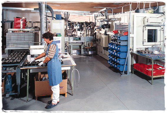
 Winding: